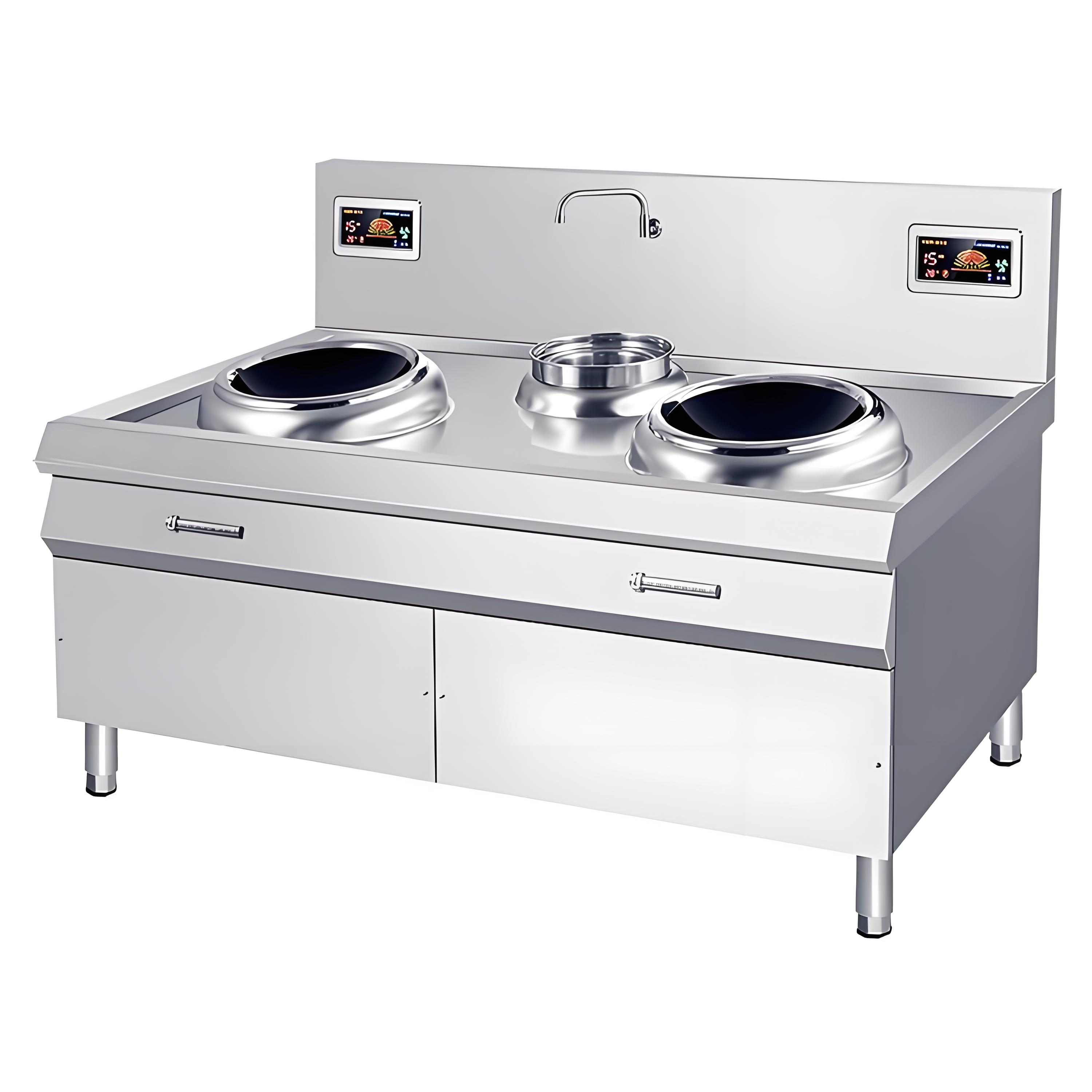
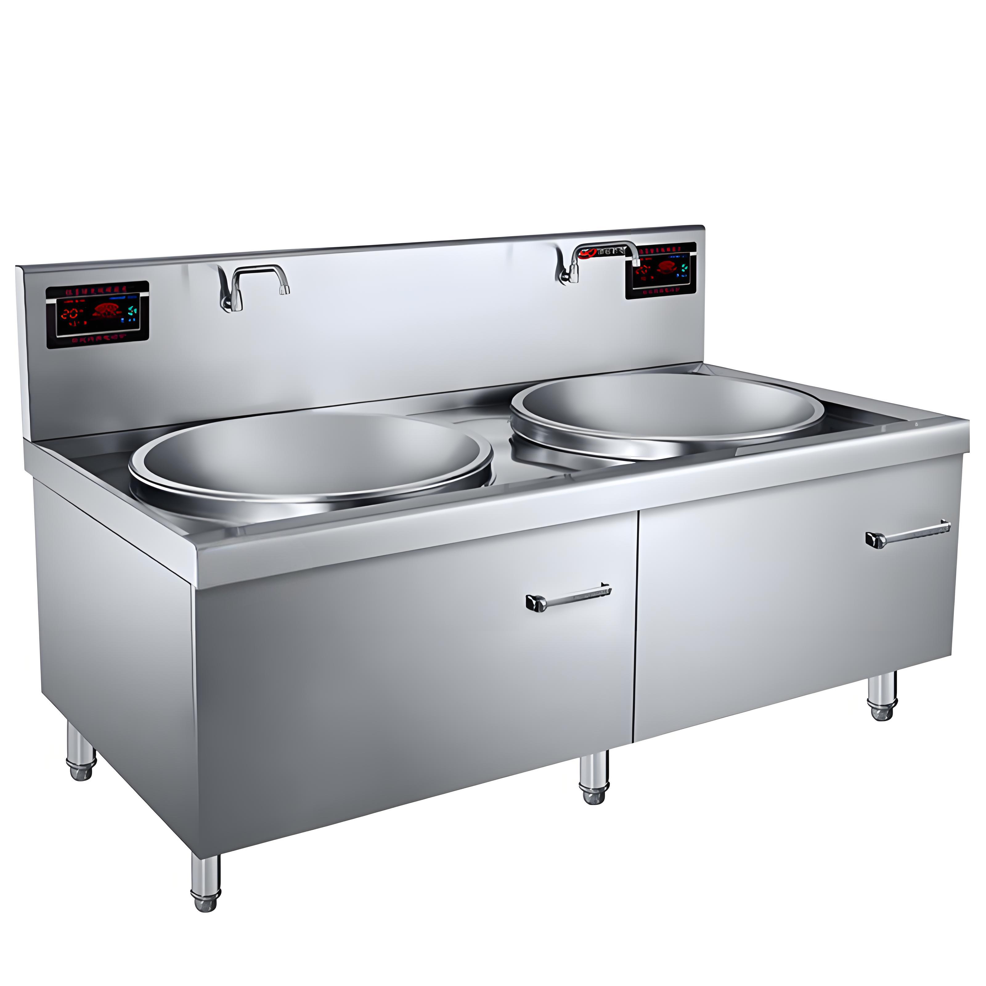
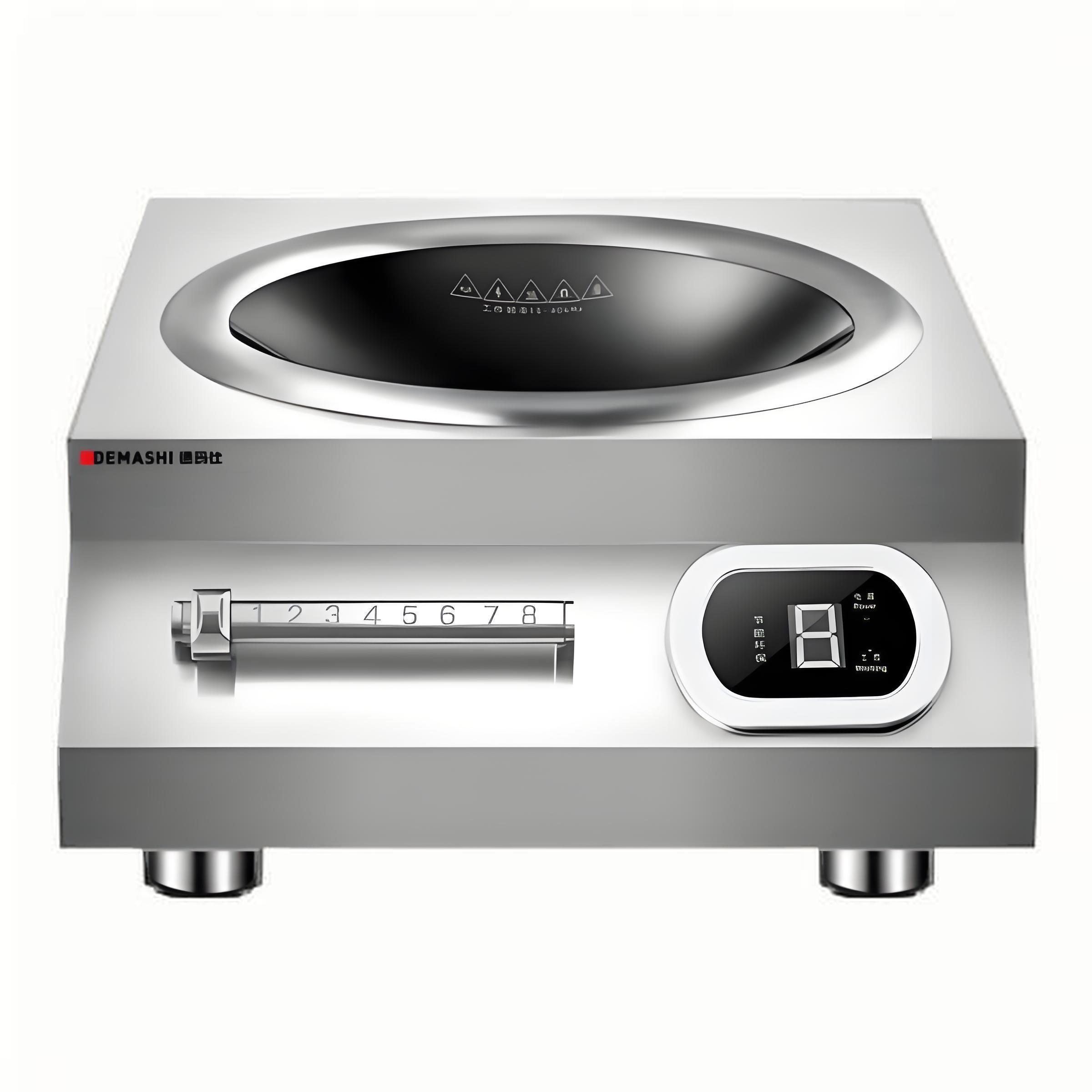
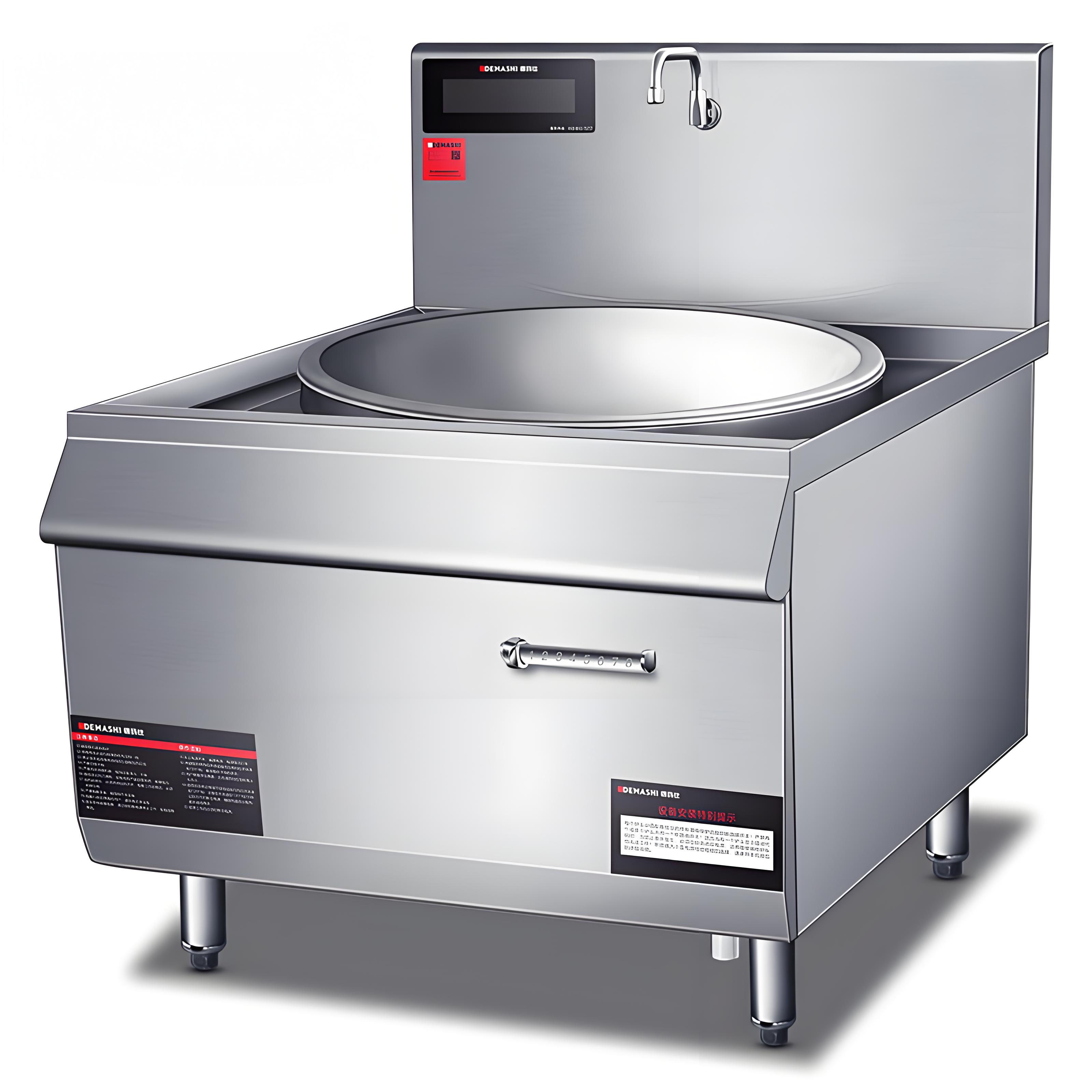
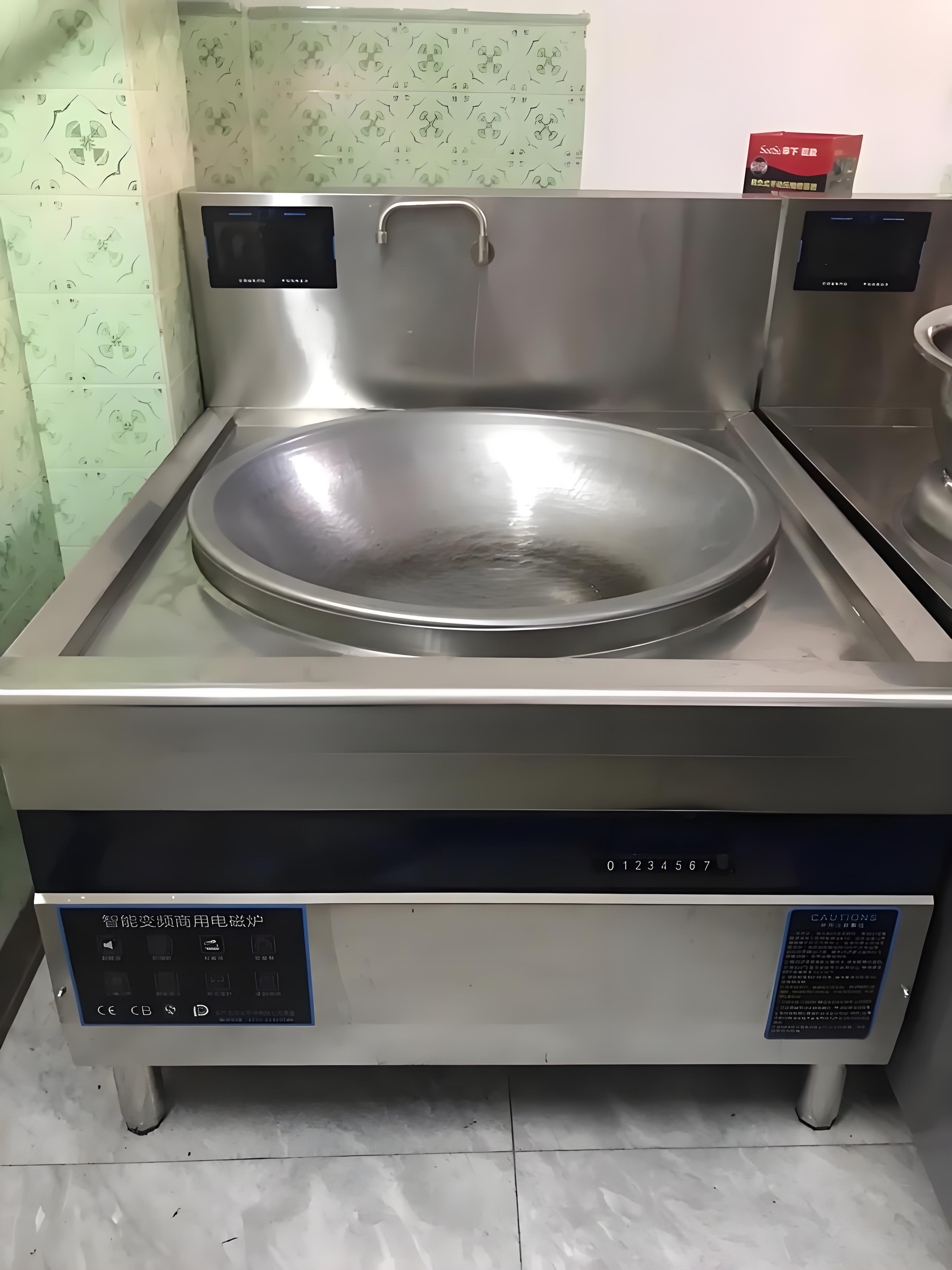
When a commercial induction cooker exhibits abnormal behavior or fails to operate, common faults and troubleshooting methods include:
1. Basic Error Codes:
E1: No pot detected
E2: Pot over-temperature protection
E3: Pot temperature sensor open circuit
E4: IGBT temperature sensor short circuit
E5: IGBT temperature sensor open circuit
E6: Voltage too low
E7: Pot temperature sensor short circuit
E8: IGBT temperature sensor short circuit
E9: Voltage too high

Notes:
After powering on, the display will light up fully once, then the red light (power indicator) blinks, the blue light stays off, and the display shows “-”.
If you turn the knob at this point and the display does not change, it indicates the knob switch is damaged or the connector is loose. Replace the potentiometer (encoder) switch.
If the issue persists, an E1 error may appear (display shows 1 or after a few seconds shows “-”), with the red light flashing simultaneously.
A. For small stir-fry cookers or flat low soup cookers, this may simply be due to no pot being placed. Place a pot and check if it works normally.
B. For large woks and other types where a pot is already present but still displays “1”, check if the coil distance has shifted, or whether the pot is induction-compatible. Use the dedicated pot supplied by the company.
C. If the red light is on, showing the current gear, and the blue light flashes briefly and goes out repeatedly, it indicates a wrong pot or the coil distance is too far.
Error details:
E2: Coil (pot) over-temperature protection. If this occurs after running for some time, check if the coil fan is working. If it is, the coil’s temperature sensor may have degraded—replace the coil’s temperature sensor holder.
E3: Pot temperature sensor open circuit—replace the pot temperature sensor holder on the coil.
E4: IGBT over-temperature. The heat dissipation fan on the mainboard isn’t running or runs too slowly. Check the fan and its connector. If these are fine, the relay might be faulty. As an emergency fix, break the relay casing to keep the contacts always connected. Notify the customer that the fan will run upon power-up, but this does not affect usage.
E5: IGBT temperature sensor open circuit. Preferably replace the mainboard or have a professional replace the aluminum temperature sensor holder.
E6: Voltage too low—indicates insufficient power supply voltage.
E7: Pot temperature sensor short circuit—replace the pot temperature sensor holder.
E8: IGBT temperature sensor short circuit. Preferably replace the mainboard or have a professional replace the aluminum temperature sensor holder.
E9: Voltage too high—power supply voltage is excessive.
2. No response on power-up, display does not light up, but turning the knob starts operation.
Remove the front panel and check if the ribbon cable to the display is broken or if the connector is loose.
3. No response on power-up, display does not light up, and turning the knob does not start operation.
Power off, remove the front panel, and inspect the transformer ribbon cable for breaks or loose connections. If the problem persists, the transformer may be damaged.
Note: Always perform this inspection with the power disconnected.
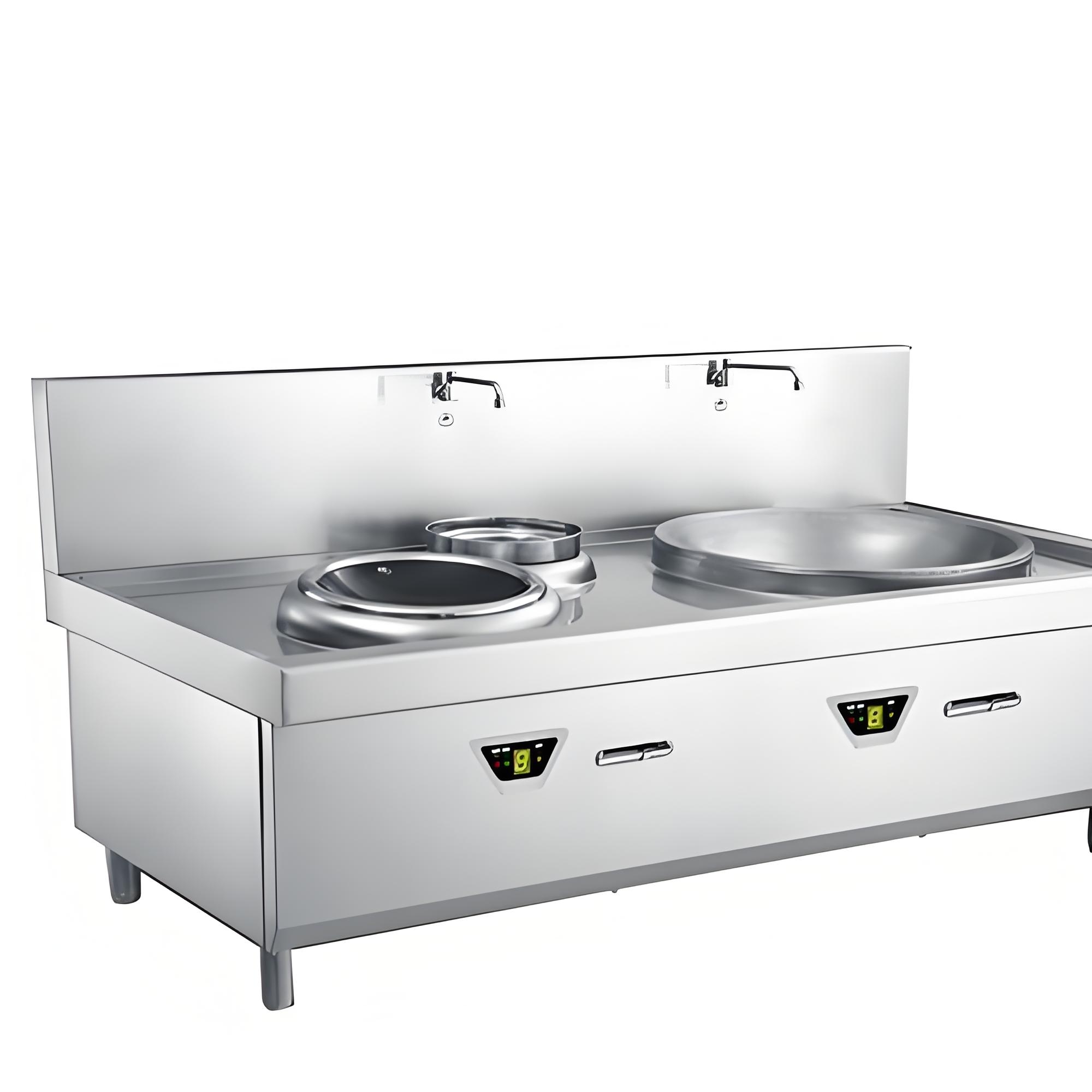
4. Display works normally on power-up, but turning the knob yields no response.
Focus on checking the knob potentiometer or encoder. See if the potentiometer and encoder rotate together when the knob is turned, if the wires are intact, and if the connector is secure. If these are fine, open the top cover and check the switch wiring connectors. Reconnect them. If still unresolved, replace the switch.
Note: If it is a potentiometer, a continuous “beep beep” alarm will sound when the switch fails.
5. Machine works normally but after some time, the front-end circuit breaker trips. Resetting allows operation again.
This is usually because the circuit breaker’s current capacity is insufficient. Advise the customer to replace it with a higher-rated breaker.
6. Cannot power up; circuit breaker trips immediately.
Disconnect the machine’s ground wire and try powering up again. If it starts, it indicates leakage. Check the coil insulation, fan, or switch. Remove and test each suspect part one by one. If removing a part stops the tripping, that part is faulty. Replace or repair it.
Note: Reconnect the ground wire after repair.
7. Fans not running.
First check if all fans are not running. If at least one fan runs, the fan control circuit is okay—inspect connectors of the non-running fans. If none of the fans run, the control circuit may be faulty. As an emergency repair, use the method described for E4.
8. Display garbled after power-up, missing segments, no buzzer sound, and shows different characters each time.
Likely damage to the main chip, crystal oscillator, or the two filter capacitors near the oscillator.
9. Circuit breaker trips on power-up.
First determine if this is due to machine failure or the customer’s circuit breaker being of poor quality.
